该视频显示:Raspberry Pi3板通过GPIO连接器连接至Mars Rover2rpi FPGA板(Cyclone IV),HDMI监视器已连接至该板。第二个监视器通过标准HDMI Raspberry Pi3连接器连接。一切都像一个带有两个监视器的系统一样工作。
我将告诉您如何进一步进行。
流行的Raspberry Pi3板具有GPIO连接器,您可以通过该GPIO连接器连接不同的扩展板:传感器,LED,步进电机驱动器等。连接器上每个引脚的具体功能取决于端口配置。 ALT2 GPIO配置允许您将连接器切换到DPI接口模式,即显示并行接口。有用于通过DPI连接VGA显示器的扩展卡。但是,首先,VGA监视器不再像HDMI常见,其次,数字接口比模拟接口更好。此外,类似的VGA扩展卡上的DAC通常以R-2-R链的形式制成,每种颜色通常不超过6位。
在ALT2模式下,GPIO引脚具有以下含义:
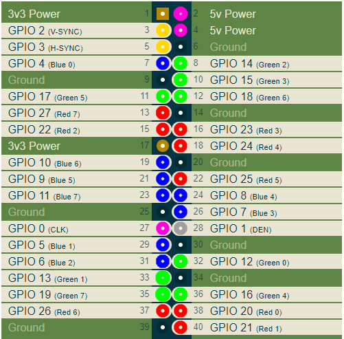
在这里,我分别以红色,绿色和蓝色为连接器的RGB引脚着色。其他重要信号是V-SYNC和H-SYNC扫描同步信号以及CLK。 CLK时钟是像素值输出到连接器的频率,它取决于所选的视频模式。
要连接数字HDMI监视器,您需要捕获DPI信号并将其转换为HDMI信号。例如,可以使用任何FPGA板来完成此操作。事实证明,Mars rover2rpi板适用于这些目的。实际上,通过特殊适配器连接此板的主要选项如下所示:
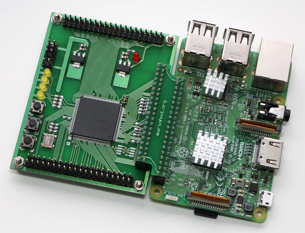
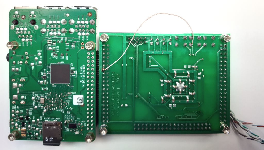
此板用于增加GPIO端口的数量,并将更多的外围设备连接到树莓派。同时,将具有此连接的4个GPIO信号用作JTAG信号,以便来自树莓派的程序可以将FPGA固件加载到FPGA中。因此,这样的标准连接不适合我,4个DPI信号丢失。幸运的是,板上的其他梳子具有与Raspberry兼容的引脚。这样我就可以将板子旋转90度,然后仍然将其连接到树莓派:

当然,我必须使用外部JTAG编程器,但这不是问题。
仍然有一个小问题。并非每个FPGA引脚都可用作时钟输入。只有几个专用引脚可用于此目的。因此,这里的结果是GPIO_0 CLK信号没有进入FPGA输入,该输入可以用作FPGA时钟频率输入。所以同样,我不得不在围巾上扔一根电线。我连接了GPIO_0和开发板的KEY [1]信号:
现在,我将简要介绍一下FPGA中的项目。形成HDMI信号的主要困难是非常高的频率。如果您看一下HDMI连接器的引脚,您会发现RGB信号现在是串行差分信号:

使用差分信号可以消除传输线上的共模噪声。在这种情况下,每个颜色信号的原始八位代码被转换为10位TMDS(最小化转换差分信令)。这是一种特殊的编码技术,可以从信号中去除直流分量,并最大程度地减少差分线上的信号切换。由于现在一个字节的颜色需要通过串行传输线传输10位,因此事实证明,串行器的时钟频率应比像素的时钟频率高10倍。例如,如果采用视频模式1280x720 60Hz,则此模式的像素频率为74.25 MHz。串行器应具有742.5MHz。
不幸的是,传统的FPGA无法做到这一点。但是,对我们来说幸运的是,FPGA内置了DDIO引脚。这些结论已经是2比1串行器的一种。也就是说,它们可以在时钟频率的上升沿和下降沿输出两个连续的位。这意味着在FPGA项目中,不能使用740MHz,而可以使用370MHz,但是需要在FPGA中使用DDIO输出元件。在这里370 MHz已经是可以达到的频率。不幸的是,1280x720模式是极限。无法在火星探测器2rpi板上安装的FPGA Cyclone IV中获得更高的分辨率。
因此,在项目中,输入像素频率CLK进入PLL,并与PLL相乘5。在该频率下,字节R,G,B转换为位对。这是由TMDS编码器完成的。 Verilog HDL的源代码如下所示:
module hdmi(
	input wire pixclk,		// 74MHz
	input wire clk_TMDS2,	// 370MHz
	input wire hsync,
	input wire vsync,
	input wire active,
	input wire [7:0]red,
	input wire [7:0]green,
	input wire [7:0]blue,
	output wire TMDS_bh,
	output wire TMDS_bl,
	output wire TMDS_gh,
	output wire TMDS_gl,
	output wire TMDS_rh,
	output wire TMDS_rl
);

wire [9:0] TMDS_red, TMDS_green, TMDS_blue;
TMDS_encoder encode_R(.clk(pixclk), .VD(red  ), .CD({vsync,hsync}), .VDE(active), .TMDS(TMDS_red));
TMDS_encoder encode_G(.clk(pixclk), .VD(green), .CD({vsync,hsync}), .VDE(active), .TMDS(TMDS_green));
TMDS_encoder encode_B(.clk(pixclk), .VD(blue ), .CD({vsync,hsync}), .VDE(active), .TMDS(TMDS_blue));

reg [2:0] TMDS_mod5=0;  // modulus 5 counter
reg [4:0] TMDS_shift_bh=0, TMDS_shift_bl=0;
reg [4:0] TMDS_shift_gh=0, TMDS_shift_gl=0;
reg [4:0] TMDS_shift_rh=0, TMDS_shift_rl=0;

wire [4:0] TMDS_blue_l  = {TMDS_blue[9],TMDS_blue[7],TMDS_blue[5],TMDS_blue[3],TMDS_blue[1]};
wire [4:0] TMDS_blue_h  = {TMDS_blue[8],TMDS_blue[6],TMDS_blue[4],TMDS_blue[2],TMDS_blue[0]};
wire [4:0] TMDS_green_l = {TMDS_green[9],TMDS_green[7],TMDS_green[5],TMDS_green[3],TMDS_green[1]};
wire [4:0] TMDS_green_h = {TMDS_green[8],TMDS_green[6],TMDS_green[4],TMDS_green[2],TMDS_green[0]};
wire [4:0] TMDS_red_l   = {TMDS_red[9],TMDS_red[7],TMDS_red[5],TMDS_red[3],TMDS_red[1]};
wire [4:0] TMDS_red_h   = {TMDS_red[8],TMDS_red[6],TMDS_red[4],TMDS_red[2],TMDS_red[0]};

always @(posedge clk_TMDS2)
begin
	TMDS_shift_bh <= TMDS_mod5[2] ? TMDS_blue_h  : TMDS_shift_bh  [4:1];
	TMDS_shift_bl <= TMDS_mod5[2] ? TMDS_blue_l  : TMDS_shift_bl  [4:1];
	TMDS_shift_gh <= TMDS_mod5[2] ? TMDS_green_h : TMDS_shift_gh  [4:1];
	TMDS_shift_gl <= TMDS_mod5[2] ? TMDS_green_l : TMDS_shift_gl  [4:1];
	TMDS_shift_rh <= TMDS_mod5[2] ? TMDS_red_h   : TMDS_shift_rh  [4:1];
	TMDS_shift_rl <= TMDS_mod5[2] ? TMDS_red_l   : TMDS_shift_rl  [4:1];
	TMDS_mod5 <= (TMDS_mod5[2]) ? 3'd0 : TMDS_mod5+3'd1;
end

assign TMDS_bh = TMDS_shift_bh[0];
assign TMDS_bl = TMDS_shift_bl[0];
assign TMDS_gh = TMDS_shift_gh[0];
assign TMDS_gl = TMDS_shift_gl[0];
assign TMDS_rh = TMDS_shift_rh[0];
assign TMDS_rl = TMDS_shift_rl[0];

endmodule

module TMDS_encoder(
	input clk,
	input [7:0] VD,	// video data (red, green or blue)
	input [1:0] CD,	// control data
	input VDE,  	// video data enable, to choose between CD (when VDE=0) and VD (when VDE=1)
	output reg [9:0] TMDS = 0
);

wire [3:0] Nb1s = VD[0] + VD[1] + VD[2] + VD[3] + VD[4] + VD[5] + VD[6] + VD[7];
wire XNOR = (Nb1s>4'd4) || (Nb1s==4'd4 && VD[0]==1'b0);
wire [8:0] q_m = {~XNOR, q_m[6:0] ^ VD[7:1] ^ {7{XNOR}}, VD[0]};

reg [3:0] balance_acc = 0;
wire [3:0] balance = q_m[0] + q_m[1] + q_m[2] + q_m[3] + q_m[4] + q_m[5] + q_m[6] + q_m[7] - 4'd4;
wire balance_sign_eq = (balance[3] == balance_acc[3]);
wire invert_q_m = (balance==0 || balance_acc==0) ? ~q_m[8] : balance_sign_eq;
wire [3:0] balance_acc_inc = balance - ({q_m[8] ^ ~balance_sign_eq} & ~(balance==0 || balance_acc==0));
wire [3:0] balance_acc_new = invert_q_m ? balance_acc-balance_acc_inc : balance_acc+balance_acc_inc;
wire [9:0] TMDS_data = {invert_q_m, q_m[8], q_m[7:0] ^ {8{invert_q_m}}};
wire [9:0] TMDS_code = CD[1] ? (CD[0] ? 10'b1010101011 : 10'b0101010100) : (CD[0] ? 10'b0010101011 : 10'b1101010100);

always @(posedge clk) TMDS <= VDE ? TMDS_data : TMDS_code;
always @(posedge clk) balance_acc <= VDE ? balance_acc_new : 4'h0;

endmodule
然后,将输出对馈送到DDIO输出,该输出在上升和下降时顺序产生一位信号。
DDIO本身可以用以下Verilog代码描述:
module ddio(
	input wire d0,
	input wire d1,
	input wire clk,
	output wire out
	);

reg r_d0;
reg r_d1;
always @(posedge clk)
begin
	r_d0 <= d0;
	r_d1 <= d1;
end
assign out = clk ? r_d0 : r_d1;
endmodule
但是它可能不会那样工作。您需要使用alter宏功能ALTDDIO_OUT才能实际使用输出DDIO元素。我的项目中使用的是ALTDDIO_OUT库组件。
可能看起来有些棘手,但可以。
您可以在github上查看用Verilog HDL编写的所有源代码。
编译后的FPGA固件被缝合到安装在Mars Rover2rpi板上的EPCS芯片中。因此,当向FPGA板供电时,FPGA将从闪存中初始化并启动。
现在我们需要谈谈Raspberry本身的配置。
我正在基于Debian Buster(版本:2020年8月)的Raspberry PI OS(32位)上进行实验,
发布日期:2020-08-20,内核版本:5.4。
有两件事要做:
- 编辑config.txt文件;
- 创建一个X服务器配置以使用两个监视器。
编辑/boot/config.txt文件时,您需要:
- 禁用i2c,i2s,spi;
- 使用覆盖dtoverlay = dpi24启用DPI模式;
- 设置视频模式1280x720 60Hz,每个DPI每点24位;
- 指定所需的帧缓冲区数量2(max_framebuffers = 2,只有这样,第二个设备/ dev / fb1才会出现)
config.txt文件的全文如下所示。
# For more options and information see
# http://rpf.io/configtxt
# Some settings may impact device functionality. See link above for details

# uncomment if you get no picture on HDMI for a default "safe" mode
#hdmi_safe=1

# uncomment this if your display has a black border of unused pixels visible
# and your display can output without overscan
disable_overscan=1

# uncomment the following to adjust overscan. Use positive numbers if console
# goes off screen, and negative if there is too much border
#overscan_left=16
#overscan_right=16
#overscan_top=16
#overscan_bottom=16

# uncomment to force a console size. By default it will be display's size minus
# overscan.
#framebuffer_width=1280
#framebuffer_height=720

# uncomment if hdmi display is not detected and composite is being output
hdmi_force_hotplug=1

# uncomment to force a specific HDMI mode (this will force VGA)
#hdmi_group=1
#hdmi_mode=1

# uncomment to force a HDMI mode rather than DVI. This can make audio work in
# DMT (computer monitor) modes
#hdmi_drive=2

# uncomment to increase signal to HDMI, if you have interference, blanking, or
# no display
#config_hdmi_boost=4

# uncomment for composite PAL
#sdtv_mode=2

#uncomment to overclock the arm. 700 MHz is the default.
#arm_freq=800

# Uncomment some or all of these to enable the optional hardware interfaces
#dtparam=i2c_arm=on
#dtparam=i2s=on
#dtparam=spi=on

dtparam=i2c_arm=off
dtparam=spi=off
dtparam=i2s=off

dtoverlay=dpi24
overscan_left=0
overscan_right=0
overscan_top=0
overscan_bottom=0
framebuffer_width=1280
framebuffer_height=720
display_default_lcd=0
enable_dpi_lcd=1
dpi_group=2
dpi_mode=87
#dpi_group=1
#dpi_mode=4
dpi_output_format=0x6f027
dpi_timings=1280 1 110 40 220 720 1 5 5 20 0 0 0 60 0 74000000 3

# Uncomment this to enable infrared communication.
#dtoverlay=gpio-ir,gpio_pin=17
#dtoverlay=gpio-ir-tx,gpio_pin=18

# Additional overlays and parameters are documented /boot/overlays/README

# Enable audio (loads snd_bcm2835)
dtparam=audio=on

[pi4]
# Enable DRM VC4 V3D driver on top of the dispmanx display stack
#dtoverlay=vc4-fkms-v3d
max_framebuffers=2

[all]
#dtoverlay=vc4-fkms-v3d
max_framebuffers=2
之后,您需要为X服务器创建一个配置文件,以在两个帧缓冲区/ dev / fb0和/ dev / fb1上使用两个监视器:
我的配置文件/usr/share/x11/xorg.conf.d/60-dualscreen.conf就像这样
Section "Device"
        Identifier      "LCD"
        Driver          "fbturbo"
        Option          "fbdev" "/dev/fb0"
        Option          "ShadowFB" "off"
        Option          "SwapbuffersWait" "true"
EndSection

Section "Device"
        Identifier      "HDMI"
        Driver          "fbturbo"
        Option          "fbdev" "/dev/fb1"
        Option          "ShadowFB" "off"
        Option          "SwapbuffersWait" "true"
EndSection

Section "Monitor"
        Identifier      "LCD-monitor"
        Option          "Primary" "true"
EndSection

Section "Monitor"
        Identifier      "HDMI-monitor"
        Option          "RightOf" "LCD-monitor"
EndSection

Section "Screen"
        Identifier      "screen0"
        Device          "LCD"
        Monitor         "LCD-monitor"
EndSection

Section "Screen"
        Identifier      "screen1"
        Device          "HDMI"
	Monitor         "HDMI-monitor"
EndSection

Section "ServerLayout"
        Identifier      "default"
        Option          "Xinerama" "on"
        Option          "Clone" "off"
        Screen 0        "screen0"
        Screen 1        "screen1" RightOf "screen0"
EndSection
好吧,如果尚未安装,那么您需要安装Xinerama。然后,桌面空间将完全扩展为两个监视器,如上面的演示视频所示。
仅此而已。现在,Raspberry Pi3所有者将能够使用两台显示器。
可以在此处查看Mars rover2rpi板的说明和图表。