这是我关于哈布雷的第一篇文章,所以我请你不要扔重物。提前致谢。
让我们从背景开始。从前,我不得不切换到ST ARM微控制器。这是由于PIC和AVR已经供不应求,并希望进行新的冒险。从面包店中的可用书以及大量关于“快速入门”的文章中,选择就在于STM32F100。
我习惯在IAR工作。是的,还有其他IDE,但是IAR功能对我来说就足够了:相对方便的编辑器,而不是不好的调试器,并且在调试过程中使用寄存器非常方便。
当我尝试进行第一个项目时,我很失望-CMSIS!其他人,但对我来说,这一直是(而且仍然是)恐怖:对我来说,有很多山毛榉,长而难以理解的结构。深入研究所有这些都没有意思。我试图编写一些示例,但意识到这不是我们的方法。
没有其他选择吗?有。IAR中内置的一个文件:iostm32f10xx4.h及其类似文件包括。一点也不差:
RCC_APB2ENR_bit.ADC1EN = 1; // ADC剩下的就是将其填充到类中并使用它。所以他做到了。一段时间后,为STM32f4xx编写代码。这里又是一次伏击-没有倾斜者。该怎么办?-写你自己。我分析了现有的自写库,并决定做一些不同的事情。这就是故事的主题。
开始
我不会谈论为调试器安装IAR和驱动程序。这里没有新内容。我的IAR 8的代码上限为32kB。选择安装在药丸板上的STM32F103控制器进行操作。
启动IAR,创建一个c ++项目,选择所需的控制器
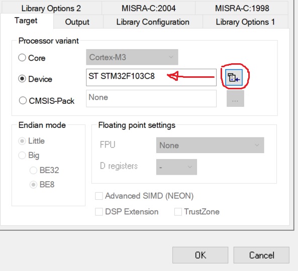
,下一步是研究文档。我们将对参考手册RM0008感兴趣。最主要的是要仔细阅读。
通常,当我教员工编程控制器时,我要完成任务-打开LED(连接到控制器腿),使用调试器,编辑寄存器并阅读文档。
RCC模块。卷起
该模块通常被遗忘。他们仅在无法使LED闪烁时才记得。
记得!要打开任何外设,您需要对其施加时钟脉冲!你不能没有它。
I / O端口位于APB2总线上。我们在文档中找到了用于控制该总线时钟的寄存器,即RCC_APB2ENR:

要启用端口C的时钟(LED刚焊接到PC13),您需要向IOPCEN位写一个。
现在,我们将找到寄存器RCC_APB2ENR的地址。其偏移量为0x18,RCC寄存器的基址为0x40021000。
为了方便使用位,让我们创建一个结构:
typedef struct
{
  uint32_t  AFIOEN         : 1;
  uint32_t                 : 1;
  uint32_t  IOPAEN         : 1;
  uint32_t  IOPBEN         : 1;
  uint32_t  IOPCEN         : 1;
  uint32_t  IOPDEN         : 1;
  uint32_t  IOPEEN         : 1;
  uint32_t                 : 2;
  uint32_t  ADC1EN         : 1;
  uint32_t  ADC2EN         : 1;
  uint32_t  TIM1EN         : 1;
  uint32_t  SPI1EN         : 1;
  uint32_t                 : 1;
  uint32_t  USART1EN       : 1;
  uint32_t                 :17;
} RCC_APB2ENR_b;
为了以后不受影响,我们将立即列出所有寄存器地址:
enum AddrRCC
{
  RCC_CR          = 0x40021000,
  RCC_CFGR        = 0x40021004,
  RCC_CIR         = 0x40021008,
  RCC_APB2RSTR    = 0x4002100C,
  RCC_APB1RSTR    = 0x40021010,
  RCC_AHBENR      = 0x40021014,
  RCC_APB2ENR     = 0x40021018,
  RCC_APB1ENR     = 0x4002101C,
  RCC_BDCR        = 0x40021020,
  RCC_CSR         = 0x40021024
};
现在仍然需要编写代码来启用外围设备:
static void EnablePort(uint8_t port_name)
{
  volatile RCC_APB2ENR_b* apb2enr = reinterpret_cast<RCC_APB2ENR_b*>(RCC_APB2ENR);
  switch (port_name)
  {
    case 'A': apb2enr->IOPAEN = 1; break;
    case 'a': apb2enr->IOPAEN = 1; break;
    case 'B': apb2enr->IOPBEN = 1; break;
    case 'b': apb2enr->IOPBEN = 1; break;
    case 'C': apb2enr->IOPCEN = 1; break;
    case 'c': apb2enr->IOPCEN = 1; break;
    case 'D': apb2enr->IOPDEN = 1; break;
    case 'd': apb2enr->IOPDEN = 1; break;
    case 'E': apb2enr->IOPEEN = 1; break;
    case 'e': apb2enr->IOPEEN = 1; break;
  }
}
使用寄存器时,请不要忘记volatile,否则,在编译器进行优化后,我们将长期寻找错误并责骂编译器开发人员。
我们执行相同的操作以启用其他外设的时钟。
结果,我们得到了以下课程(未列出所有内容):
STM32F1xx_RCC.h
#pragma once
#include "stdint.h"
namespace STM32F1xx
{
  class RCC
  {
  protected:
    enum AddrRCC
    {
      RCC_CR          = 0x40021000,
      RCC_CFGR        = 0x40021004,
      RCC_CIR         = 0x40021008,
      RCC_APB2RSTR    = 0x4002100C,
      RCC_APB1RSTR    = 0x40021010,
      RCC_AHBENR      = 0x40021014,
      RCC_APB2ENR     = 0x40021018,
      RCC_APB1ENR     = 0x4002101C,
      RCC_BDCR        = 0x40021020,
      RCC_CSR         = 0x40021024
    };

    typedef struct {
      uint32_t  HSION          : 1;
      uint32_t  HSIRDY         : 1;
      uint32_t                 : 1;
      uint32_t  HSI_TRIM       : 5;
      uint32_t  HSI_CAL        : 8;
      uint32_t  HSEON          : 1;
      uint32_t  HSERDY         : 1;
      uint32_t  HSEBYP         : 1;
      uint32_t  CSSON          : 1;
      uint32_t                 : 4;
      uint32_t  PLLON          : 1;
      uint32_t  PLLRDY         : 1;
      uint32_t                 : 6;
    } RCC_CR_b;

    typedef struct {
      uint32_t  SW             : 2;
      uint32_t  SWS            : 2;
      uint32_t  HPRE           : 4;
      uint32_t  PPRE1          : 3;
      uint32_t  PPRE2          : 3;
      uint32_t  ADC_PRE        : 2;
      uint32_t  PLLSRC         : 1;
      uint32_t  PLLXTPRE       : 1;
      uint32_t  PLLMUL         : 4;
      uint32_t  USBPRE         : 1;
      uint32_t                 : 1;
      uint32_t  MCO            : 3;
      uint32_t                 : 5;
    } RCC_CFGR_b;

    typedef struct
    {
      uint32_t  TIM2EN         : 1;
      uint32_t  TIM3EN         : 1;
      uint32_t  TIM4EN         : 1;
      uint32_t                 : 8;
      uint32_t  WWDGEN         : 1;
      uint32_t                 : 2;
      uint32_t  SPI2EN         : 1;
      uint32_t                 : 2;
      uint32_t  USART2EN       : 1;
      uint32_t  USART3EN       : 1;
      uint32_t                 : 2;
      uint32_t  I2C1EN         : 1;
      uint32_t  I2C2EN         : 1;
      uint32_t  USBEN          : 1;
      uint32_t                 : 1;
      uint32_t  CANEN          : 1;
      uint32_t                 : 1;
      uint32_t  BKPEN          : 1;
      uint32_t  PWREN          : 1;
      uint32_t                 : 3;
    } RCC_APB1ENR_b;

    typedef struct
    {
      uint32_t  AFIOEN         : 1;
      uint32_t                 : 1;
      uint32_t  IOPAEN         : 1;
      uint32_t  IOPBEN         : 1;
      uint32_t  IOPCEN         : 1;
      uint32_t  IOPDEN         : 1;
      uint32_t  IOPEEN         : 1;
      uint32_t                 : 2;
      uint32_t  ADC1EN         : 1;
      uint32_t  ADC2EN         : 1;
      uint32_t  TIM1EN         : 1;
      uint32_t  SPI1EN         : 1;
      uint32_t                 : 1;
      uint32_t  USART1EN       : 1;
      uint32_t                 :17;
    } RCC_APB2ENR_b;

    typedef struct {
      uint32_t  DMAEN          : 1;
      uint32_t                 : 1;
      uint32_t  SRAMEN         : 1;
      uint32_t                 : 1;
      uint32_t  FLITFEN        : 1;
      uint32_t                 : 1;
      uint32_t  CRCEN          : 1;
      uint32_t                 :25;
    } RCC_AHBENR_r;

  public:
    static void EnablePort(uint8_t port_name)
    {
      volatile RCC_APB2ENR_b* apb2enr = reinterpret_cast<RCC_APB2ENR_b*>(RCC_APB2ENR);
      switch (port_name)
      {
        case 'A': apb2enr->IOPAEN = 1; break;
        case 'a': apb2enr->IOPAEN = 1; break;
        case 'B': apb2enr->IOPBEN = 1; break;
        case 'b': apb2enr->IOPBEN = 1; break;
        case 'C': apb2enr->IOPCEN = 1; break;
        case 'c': apb2enr->IOPCEN = 1; break;
        case 'D': apb2enr->IOPDEN = 1; break;
        case 'd': apb2enr->IOPDEN = 1; break;
        case 'E': apb2enr->IOPEEN = 1; break;
        case 'e': apb2enr->IOPEEN = 1; break;
      }
    }

    static void DisablePort(char port_name)
    {
      volatile RCC_APB2ENR_b* apb2enr = reinterpret_cast<RCC_APB2ENR_b*>(RCC_APB2ENR);
      switch (port_name)
      {
        case 'A': apb2enr->IOPAEN = 0; break;
        case 'a': apb2enr->IOPAEN = 0; break;
        case 'B': apb2enr->IOPBEN = 0; break;
        case 'b': apb2enr->IOPBEN = 0; break;
        case 'C': apb2enr->IOPCEN = 0; break;
        case 'c': apb2enr->IOPCEN = 0; break;
        case 'D': apb2enr->IOPDEN = 0; break;
        case 'd': apb2enr->IOPDEN = 0; break;
        case 'E': apb2enr->IOPEEN = 0; break;
        case 'e': apb2enr->IOPEEN = 0; break;
      }
    }

    static void EnableAFIO()
    {
      volatile RCC_APB2ENR_b* apb2enr = reinterpret_cast<RCC_APB2ENR_b*>(RCC_APB2ENR);
      apb2enr->AFIOEN = 1;
    }

    static void DisableAFIO()
    {
      volatile RCC_APB2ENR_b* apb2enr = reinterpret_cast<RCC_APB2ENR_b*>(RCC_APB2ENR);
      apb2enr->AFIOEN = 0;
    }

    static void EnableI2C(int PortNumber)
    {
      switch (PortNumber)
      {
        case 1:
        {
          volatile RCC_APB1ENR_b* apb1enr = reinterpret_cast<RCC_APB1ENR_b*>(RCC_APB1ENR);
          apb1enr->I2C1EN = 1;
          break;
        }
        case 2:
        {
          volatile RCC_APB1ENR_b* apb1enr = reinterpret_cast<RCC_APB1ENR_b*>(RCC_APB1ENR);
          apb1enr->I2C2EN = 1;
          break;
        }

      }
    }

    static void EnableUART(int PortNumber)
    {
      switch (PortNumber)
      {
        case 1:
        {
          volatile RCC_APB2ENR_b* apb2enr = reinterpret_cast<RCC_APB2ENR_b*>(RCC_APB2ENR);
          apb2enr->USART1EN = 1;
          break;
        }
        case 2:
        {
          volatile RCC_APB1ENR_b* apb1enr = reinterpret_cast<RCC_APB1ENR_b*>(RCC_APB1ENR);
          apb1enr->USART2EN = 1;
          break;
        }
        case 3:
        {
          volatile RCC_APB1ENR_b* apb1enr = reinterpret_cast<RCC_APB1ENR_b*>(RCC_APB1ENR);
          apb1enr->USART3EN = 1;
          break;
        }

      }
    }

    static void DisableUART(int PortNumber)
    {
      switch (PortNumber)
      {
        case 1:
        {
          volatile RCC_APB2ENR_b* apb2enr = reinterpret_cast<RCC_APB2ENR_b*>(RCC_APB2ENR);
          apb2enr->USART1EN = 0;
          break;
        }
        case 2:
        {
          volatile RCC_APB1ENR_b* apb1enr = reinterpret_cast<RCC_APB1ENR_b*>(RCC_APB1ENR);
          apb1enr->USART2EN = 0;
          break;
        }
        case 3:
        {
          volatile RCC_APB1ENR_b* apb1enr = reinterpret_cast<RCC_APB1ENR_b*>(RCC_APB1ENR);
          apb1enr->USART3EN = 0;
          break;
        }
      }
    }

    static void EnableSPI(int PortNumber)
    {
      switch (PortNumber)
      {
        case 1:
        {
          volatile RCC_APB2ENR_b* apb2enr = reinterpret_cast<RCC_APB2ENR_b*>(RCC_APB2ENR);
          apb2enr->SPI1EN = 1;
          break;
        }
        case 2:
        {
          volatile RCC_APB1ENR_b* apb1enr = reinterpret_cast<RCC_APB1ENR_b*>(RCC_APB1ENR);
          apb1enr->SPI2EN = 1;
          break;
        }
      }
    }

    static void DisableSPI(int PortNumber)
    {
      switch (PortNumber)
      {
        case 1:
        {
          volatile RCC_APB2ENR_b* apb2enr = reinterpret_cast<RCC_APB2ENR_b*>(RCC_APB2ENR);
          apb2enr->SPI1EN = 0;
          break;
        }
        case 2:
        {
          volatile RCC_APB1ENR_b* apb1enr = reinterpret_cast<RCC_APB1ENR_b*>(RCC_APB1ENR);
          apb1enr->SPI2EN = 0;
          break;
        }
      }
    }

    static void EnableDMA()
    {
      volatile RCC_AHBENR_r* ahbenr = reinterpret_cast<RCC_AHBENR_r*>(RCC_AHBENR);
      ahbenr->DMAEN = 1;
    }

    static void DisableDMA()
    {
      volatile RCC_AHBENR_r* ahbenr = reinterpret_cast<RCC_AHBENR_r*>(RCC_AHBENR);
      ahbenr->DMAEN = 0;
    }
  };
}
现在,您可以在main.cpp中附加文件并使用:
#include "STM32F1xx_RCC.h"

using namespace STM32F1xx;

int main()
{
  RCC::EnablePort('c');
  return 0;
}
现在,您可以使用端口了。通用输入输出
打开文档中的通用和备用功能I / O部分。查找端口位配置表:

CNF [1:0]位设置端口操作模式(模拟输入,数字输入,输出),MODE [1:0]位对应于输出模式下的端口操作速度。
让我们看一下GPIOx_CRL和GPIOx_CRH寄存器(x = A,B,C,...),您

会看到这些位按顺序排列:
CNF [1:0],MODE [1:0],
然后使用端口的操作模式创建常量
enum mode_e
{
  ANALOGINPUT             = 0,
  INPUT                   = 4,
  INPUTPULLED             = 8,

  OUTPUT_10MHZ            = 1,
  OUTPUT_OD_10MHZ         = 5,
  ALT_OUTPUT_10MHZ        = 9,
  ALT_OUTPUT_OD_10MHZ     = 13,

  OUTPUT_50MHZ            = 3,
  OUTPUT_OD_50MHZ         = 7,
  ALT_OUTPUT_50MHZ        = 11,
  ALT_OUTPUT_OD_50MHZ     = 15,

  OUTPUT_2MHZ             = 2,
  OUTPUT_OD_2MHZ          = 6,
  ALT_OUTPUT_2MHZ         = 10,
  ALT_OUTPUT_OD_2MHZ      = 14,

  OUTPUT                  = 3,
  OUTPUT_OD               = 7,
  ALT_OUTPUT              = 11,
  ALT_OUTPUT_OD           = 15
};
那么配置方法将如下所示:
// pin_number -
void Mode(mode_e mode)
{
  uint32_t* addr;
  if(pin_number > 7)
    addr = reinterpret_cast<uint32_t*>(GPIOA_CRH);
  else
    addr = reinterpret_cast<uint32_t*>(GPIOA_CRL);

  int bit_offset;
  if(pin_number > 7)
    bit_offset = (pin_number - 8) * 4;
  else
    bit_offset = pin_number * 4;

  uint32_t mask = ~(15 << bit_offset);
  *addr &= mask;
  *addr |= ((int)mode) << bit_offset;
}
现在我们可以为选择模式提供更方便的方法:
    void ModeInput()              { Mode(INPUT);         }
    void ModeAnalogInput()        { Mode(ANALOGINPUT);   }
    void ModeInputPulled()        { Mode(INPUTPULLED);   }
    void ModeOutput()             { Mode(OUTPUT);        }
    void ModeOutputOpenDrain()    { Mode(OUTPUT_OD);     }
    void ModeAlternate()          { Mode(ALT_OUTPUT);    }
    void ModeAlternateOpenDrain() { Mode(ALT_OUTPUT_OD); }
在文档中,我们找到端口的控制寄存器的地址并列出它们:
enum AddrGPIO
{
  PortA           = 0x40010800,
  GPIOA_CRL       = 0x40010800,
  GPIOA_CRH       = 0x40010804,
  GPIOA_IDR       = 0x40010808,
  GPIOA_ODR       = 0x4001080C,
  GPIOA_BSRR      = 0x40010810,
  GPIOA_BRR       = 0x40010814,
  GPIOA_LCKR      = 0x40010818,
  PortB           = 0x40010C00,
  PortC           = 0x40011000,
  PortD           = 0x40011400,
  PortE           = 0x40011800,
  PortF           = 0x40011C00,
  PortG           = 0x40012000
};长期以来考虑使用基地址和偏移量或绝对地址。最后,我停在了后者。这增加了一些开销,但是在调试过程中更容易在内存中查找。
让我们现代化该方法:
if(pin_number > 7)
  addr = reinterpret_cast<uint32_t*>(GPIOA_CRH - PortA + PortAddr);
else
  addr = reinterpret_cast<uint32_t*>(GPIOA_CRL - PortA + PortAddr);
也许有人会抽搐,但我还没有想出一个更漂亮的人。
要将支路转移到所需的逻辑状态,只需将相应的位写入ODRx寄存器即可。例如,像这样:
void Set(bool st)
{
  uint32_t* addr;
  addr = reinterpret_cast<uint32_t*>(GPIOA_ODR - PortA + PortAddr);

  if(st)
    *addr |= 1 << pin_number;
  else
  {
    int mask = ~(1 << pin_number);
    *addr &= mask;
  }
}
您还可以使用GPIOx_BSRR寄存器来控制状态。
以此类推,我们提供了读取端口状态的方法,配置和初始化的方法(请不要忘记启用时钟)。结果,我们得到了以下用于端口的类:
STM32F1xx_Pin.h
#pragma once
#include <stdint.h>
#include "STM32F1xx_RCC.h"

namespace STM32F1xx
{
  class Pin
  {
  public:
    enum mode_e
    {
      ANALOGINPUT             = 0,
      INPUT                   = 4,
      INPUTPULLED             = 8,

      OUTPUT_10MHZ            = 1,
      OUTPUT_OD_10MHZ         = 5,
      ALT_OUTPUT_10MHZ        = 9,
      ALT_OUTPUT_OD_10MHZ     = 13,

      OUTPUT_50MHZ            = 3,
      OUTPUT_OD_50MHZ         = 7,
      ALT_OUTPUT_50MHZ        = 11,
      ALT_OUTPUT_OD_50MHZ     = 15,

      OUTPUT_2MHZ             = 2,
      OUTPUT_OD_2MHZ          = 6,
      ALT_OUTPUT_2MHZ         = 10,
      ALT_OUTPUT_OD_2MHZ      = 14,

      OUTPUT                  = 3,
      OUTPUT_OD               = 7,
      ALT_OUTPUT              = 11,
      ALT_OUTPUT_OD           = 15
    };

  private:
    enum AddrGPIO
    {
      PortA           = 0x40010800,
      GPIOA_CRL       = 0x40010800,
      GPIOA_CRH       = 0x40010804,
      GPIOA_IDR       = 0x40010808,
      GPIOA_ODR       = 0x4001080C,
      GPIOA_BSRR      = 0x40010810,
      GPIOA_BRR       = 0x40010814,
      GPIOA_LCKR      = 0x40010818,
      PortB           = 0x40010C00,
      PortC           = 0x40011000,
      PortD           = 0x40011400,
      PortE           = 0x40011800,
      PortF           = 0x40011C00,
      PortG           = 0x40012000
    };

  private:
    int   pin_number;
    int   PortAddr;

  public:
    Pin()                               { }
    Pin(char port_name, int pin_number) { Init(port_name, pin_number); }
    ~Pin()
    {
      Off();
      ModeAnalogInput();
    }
  public:
    void Init(char port_name, int pin_number)
    {
      this->pin_number = pin_number;
      RCC::EnablePort(port_name);
      switch (port_name)
      {
        case 'A': PortAddr = PortA; break;
        case 'a': PortAddr = PortA; break;
        case 'B': PortAddr = PortB; break;
        case 'b': PortAddr = PortB; break;
        case 'C': PortAddr = PortC; break;
        case 'c': PortAddr = PortC; break;
        case 'D': PortAddr = PortD; break;
        case 'd': PortAddr = PortD; break;
        case 'E': PortAddr = PortE; break;
        case 'e': PortAddr = PortE; break;
      }
    }

    void ModeInput()              { Mode(INPUT);         }
    void ModeAnalogInput()        { Mode(ANALOGINPUT);   }
    void ModeInputPulled()        { Mode(INPUTPULLED);   }
    void ModeOutput()             { Mode(OUTPUT);        }
    void ModeOutputOpenDrain()    { Mode(OUTPUT_OD);     }
    void ModeAlternate()          { Mode(ALT_OUTPUT);    }
    void ModeAlternateOpenDrain() { Mode(ALT_OUTPUT_OD); }

    void NoPullUpDown()
    {
      uint32_t* addr;
      if(pin_number > 7)
        addr = reinterpret_cast<uint32_t*>(GPIOA_CRH - PortA + PortAddr);
      else
        addr = reinterpret_cast<uint32_t*>(GPIOA_CRL - PortA + PortAddr);

      int bit_offset;
      if(pin_number > 7)
        bit_offset = (pin_number - 8) * 4;
      else
         bit_offset = pin_number * 4;

      int mask = ~((1 << 3) << bit_offset);
      *addr &= mask;
    }

    void Mode(mode_e mode)
    {
      uint32_t* addr;
      if(pin_number > 7)
        addr = reinterpret_cast<uint32_t*>(GPIOA_CRH - PortA + PortAddr);
      else
        addr = reinterpret_cast<uint32_t*>(GPIOA_CRL - PortA + PortAddr);

      int bit_offset;
      if(pin_number > 7)
        bit_offset = (pin_number - 8) * 4;
      else
        bit_offset = pin_number * 4;

      uint32_t mask = ~(15 << bit_offset);
      *addr &= mask;
      *addr |= ((int)mode) << bit_offset;
    }

    void Set(bool st)
    {
      uint32_t* addr;
      addr = reinterpret_cast<uint32_t*>(GPIOA_ODR - PortA + PortAddr);

      if(st)
        *addr |= 1 << pin_number;
      else
      {
        int mask = ~(1 << pin_number);
        *addr &= mask;
      }
    }

    void On()
    {
      uint32_t* addr;
      addr = reinterpret_cast<uint32_t*>(GPIOA_ODR - PortA + PortAddr);
      int bit_offset = pin_number;
      *addr |= 1 << bit_offset;
    }

    void Off()
    {
      uint32_t* addr;
      addr = reinterpret_cast<uint32_t*>(GPIOA_ODR - PortA + PortAddr);
      int bit_offset = pin_number;
      int mask = ~(1 << bit_offset);
      *addr &= mask;
    }

    bool Get()
    {
      uint32_t* addr = reinterpret_cast<uint32_t*>(GPIOA_IDR - PortA + PortAddr);
      int bit_offset = pin_number;
      int mask = (1 << bit_offset);
      bool ret_val = (*addr & mask);
      return ret_val;
    }
  };
};
好吧,让我们尝试:
#include "STM32F1xx_Pin.h"

using namespace STM32F1xx;

Pin led('c', 13);

int main()
{
  led.ModeOutput();
  led.On();
  led.Off();
  return 0;
}
我们通过调试器,确保LED首先点亮(在led.ModeOutput();之后),然后熄灭(led.On();),然后再次点亮(led.Off();)。这是因为LED通过电源线连接到支脚。因此,当引脚为低电平时,LED点亮。
总数不大
在本文中,我尝试(希望能解决)展示了如何简化您的生活,使代码更具可读性。反之亦然-如何不这样做。每个人都会自己决定。
可以为CMSIS编写包装程序,但这并不有趣。
感谢您的时间。如果您对续集感兴趣,请告诉我。